There is a specific kind of panic that sets in when you are assembling a prototype that looked perfect in CAD.
The PCB mounts perfectly. The enclosure lid aligns beautifully. The screws are the right length. But as you try to close the case, it springs back open. You push harder. Something crunches—something that should not crunch.
In most projects, cabling is the only subsystem that is guaranteed to be present, guaranteed to be physical, and almost always ignored until it breaks something.
You have forgotten the Invisible Spaghetti.
In the digital realm, we connect Point A to Point B with a schematic line, or maybe a 3D spline that passes ghost-like through a battery holder. We assume the wires will "just fit" into the empty spaces, like water filling a cup.
But wires are not water. They are physical objects with stiffness, volume, and a bad attitude. That attitude only gets worse with heat, vibration, and tight packaging. Here is why you need to stop treating cabling as an afterthought.
Screen World vs. The Copper Snake
We often talk about the gap between Screen World and Real World. Nowhere is this gap wider than in cabling.
In Screen World, a wire has zero thickness and infinite flexibility. In Real World, a bundle of six 18 AWG wires is basically a stiff plastic rod that refuses to bend tighter than a 20mm radius and happily pries your enclosure apart if you try.
If you don’t model the route, the route will model you—usually by forcing you to cut a hole in your beautiful enclosure with a Dremel tool.
1. Account for the Connector Shadow
It is easy to check if the connector header fits on the PCB. But have you checked the "connector shadow"?
A JST-XH connector isn't just the white plastic block. It is the block, plus the crimp sticking out the top, plus the 15mm of stiff wire that comes out of the crimp before it can safely bend.
- As a rule of thumb, budget at least 10–15mm of straight wire before the first bend on small board connectors.
- For larger power connectors, treat the first 20–30mm as nearly rigid.
The Fix
Model a "keep-out" cylinder or box above every connector in your CAD. If that volume hits your lid, your battery, or your heatsink, you have a problem that no amount of electrical tape will solve.
2. Add a Service Loop (Always)
Imagine you need to change a battery. You unscrew the lid and lift it up.
Scenario A: The wires are tight as guitar strings. You rip the connector off the board instantly.
Scenario B: You have 50mm of slack (a service loop) that allows the lid to sit next to the unit while you work.
Screen World loves Scenario A because it looks tidy. Real World technicians pray for Scenario B.
- For lids that hinge or lift off, plan at least 40–60mm of slack in the harness.
- Make sure there is a defined pocket or cavity where that slack can actually live when the unit is closed.
The Fix
Budget air volume for the slack. Wires need a place to fold up when the case is closed. If you don't design a pocket for the slack, the slack will sit on top of your hottest component—or get pinched in the joint.
3. Respect Minimum Bend Radius
If you try to bend a thick cable at 90 degrees instantly, two things happen: the insulation turns white from stress, and the copper strands inside start to fracture.
Heavy gauge power wires or shielded data cables act more like springs than string. They exert force. I have seen poorly routed cables actually push surface-mount components off a PCB over time just from the spring tension.
- Safe starting point: keep the bend radius at 6–10× the overall cable diameter unless the manufacturer says otherwise.
- For shielded or high-strand-count cables, err toward the higher end of that range.
The Fix
Don’t route straight lines. Route arcs. If your CAD spline has a sharp corner, you are lying to yourself—and setting up a future failure mode.
Bundle up a wire harness and it stores energy. Close the lid and that energy is trying to escape. Over time, that spring force shows up as cracked solder joints, lifted components, buzzing vibrations, or cases that never quite stay closed.
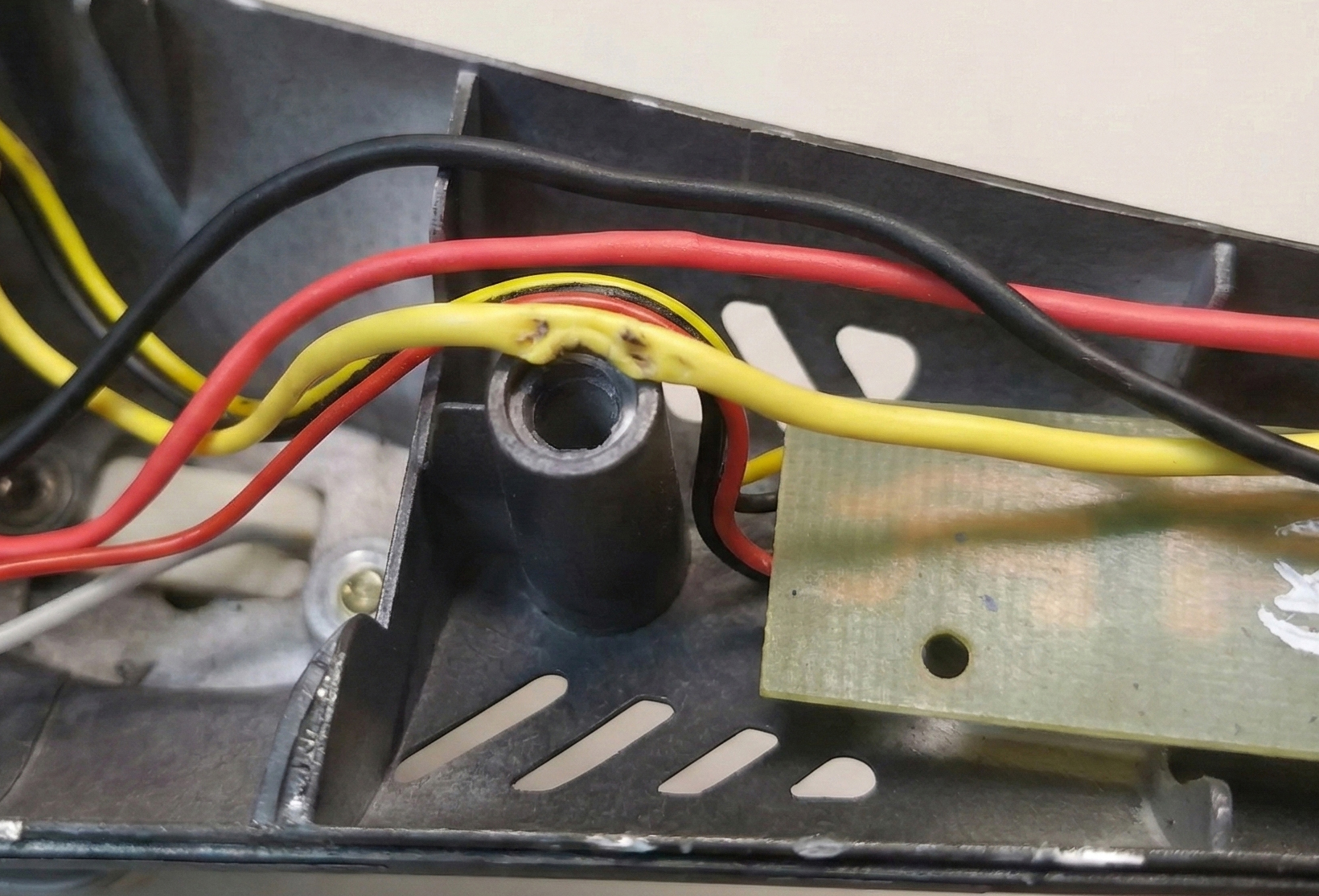
4. Prevent Chafing with Proper Restraints
Vibration is the enemy. If a wire touches a sharp metal edge, or even a rough plastic edge, and the device vibrates, it is only a matter of time before you have a short circuit.
We often see "floating" wires in designs—wires that just span across the enclosure air gap. These act like guitar strings, resonating until they fatigue or rub through. A vibrating wire can saw through insulation in weeks, not years.
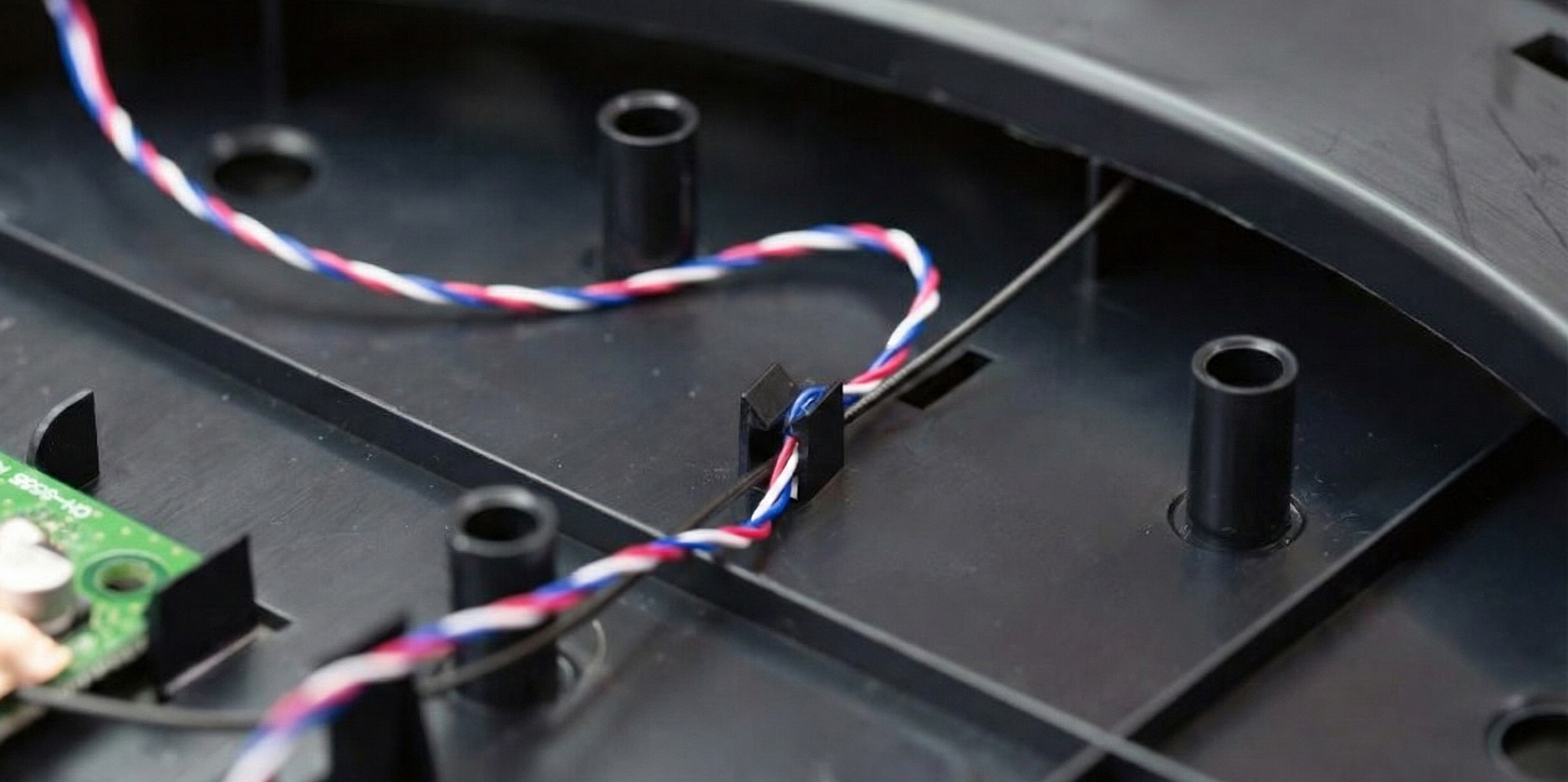
The Fix
Tie it down. Add features to your plastic parts specifically to hold wires. Ribs, clips, or zip-tie anchors are not "extra" features; they are essential structural components of the harness.
5. Verify the Assembly Sequence
Just like with mechanical assembly, the order of operations matters. Can you actually reach the plug when the board is screwed down?
If you have to use a pair of tweezers and hold your breath to seat a connector, your design has failed. If the production team hates building it, the quality will suffer.
- Walk through the assembly step-by-step in CAD: “What gets plugged in, when, and with how much access?”
- Make sure the last connector can be reached with gloved hands, not just mouse clicks.
Pro Tip: Keep Wires Off Hot Surfaces
Wires love to find their way onto the worst possible real estate: heatsinks, power resistors, regulators, and anything bolted to a metal chassis.
Insulation gets soft with temperature, which makes it easier for vibration to rub through. A harness that looked fine at room temperature becomes a melty, chafing mess at 70°C.
The Fix
Reserve "no-wire zones" around hot components and give the harness its own supported path. If a wire has to cross a hot area, do it once, at 90°, with proper strain relief and clearance.
Treat Wires Like Parts
The solution is a shift in mindset. A wire harness is not "stuffing." It is a mechanical component. It has a BOM line item, a mass, a volume, and tolerance requirements.
When you take the time to model the "spaghetti"—to design the channels, the tie-down points, and the service loops—you stop fighting the chaos.
Wire Routing Checklist
- Model connector shadows (including 10–20mm of stiff tail).
- Budget a proper service loop wherever lids or panels move.
- Respect minimum bend radii (6–10× cable diameter).
- Add restraints so no span is left vibrating in free air.
- Protect wires from sharp edges and hot components.
- Validate the plug-in sequence with real-world access in mind.
- Reserve actual volume in the enclosure for the harness to live.
You get an assembly that doesn't spring open. You get a product that doesn't short out after a week of vibration. And most importantly, you get the satisfaction of opening a case and seeing everything exactly where it should be.
If your prototypes keep pinching wires, popping lids, or failing in vibration, this is exactly the kind of "Invisible Spaghetti" we help untangle at Kotatsu—before it reaches your customer.
Don't let the invisible parts be the ones that stop you from shipping.
Related reading: Design for Assemblability: Thinking in Hands, Not Parts